Thursday, March 24, 2016

Day 9 MAX Power Applications Source Modeling

Part 1: Maximum power 


Grapfrom formula


The condition so that gaining maximum power: Rl = Rth. The formula of P in terms of Rl: P(Rl) = [Vth^2]/(Rl +Rth) * Rl. 


The analysis of power formula in terms of Rl. P(Rl) = f(Rl)*g(Rl). f = [Vth]/(Rl +Rth), g= Vth* Rl. Graph of P is the combination of f*g. 


The maximum power problem. Firstly, we need to find the Thevinen circuit, with Vth and Rth. The maximum power of Rl occurs when Rl = Rth. 


Require Ah for the motor. Based on the table at 12V for the maximum power at 67.9 A, we find the resistor of the CIM motor 0.177Ohm. 2 CIM and 1 brushless motor connected in parallel. From the table we also have the brushless motor 0.13 Ohm. Req = Rl = Rth=0.052Ohm. Then we find the Power maximum = 2.7kW. Then, we find the Ah, the energy the motor  per the energy its energy using in 1A in 1hour. 

Professor's instruction


We do a maximum power problem. We get the Thevinen circuit, Vth = 22V and Rth = 9 Ohm. The we calculate the maximum power P=(Vth^2) / (4*Rth) = 13.44 W. 

Part 2: Maximum power lab

Purpose: The lab is to help verify the maximum power theory, then observe and analyze any difference between the theory and the experiment. 

According to the schematic circuit, we set up the breadboard, analog, wires, and resistors with different values

The resistors and the V(Rl)'s values are measured. Rth = 4.63 kOhm. So, we expect the Rl for maximum power is also 4.63 kOhm. 


Form the table and the graph, maximum power is slightly different form our expectation, Rl = 4.98k Ohm instead of 4.63kOhm, so it may be because the internal resistor in the analog. 


Explanation of professor Mason for the theoretical graph and the experimental graph of power. There is the additional resistance in the analog causing the graph slightly shift to the right. 

Part 3:Source modeling 
Practical voltage and current sources are not ideal due to their internal resistances or source resistances. Hence,
Voltage division: the load voltage is Vl = [Rl/(Rs+Rl)] *Vs.
Current division: the load current is Il = [Rp/(Rp+Rl)] * Is

The example for the source modeling. Based on the difference between the Vl with and without Rl we have the voltage drop across the internal resistor Rs= (Vs-Vl)/Il.  we need to find the current of the circuit. We find current using the relation between the power and voltage load and current load. P=Vl^2/Rl = Il^2*Rl. Rs=2.4 Ohm. So, Vs=12.4V, Rs=2.4 Ohm. 

The resistance measurement

In the very last moment of the class, we study about the resistance measurement from the Wheatstone bridge. Analyzing the circuit with the voltage division, when the bridge balance v1=v2 and R2R3 = R1Rx. If R1=R3, Rx=R2. So, we can measure the resistance based on the Wheatstone bridge. 

Summary:

Today, we study about the maximum power and the condition of Rl to gain the maximum power: Rl=Rth. Then we apply its in to the robot model, as well as converting the energy into Ah. We also do the maximum power lab, and observe the difference between the theory and experiment due to the internal resistance. After that, we discuss about the source modeling and its internal resistance. Lastly, we study about the Wheatstone bridge and its application in measuring the resistance. 


Day 6: Notes MESH ANALYSIS and Transistors/ Mesh Analysis and A BJT Curve Tracer Lab

Day 6: Notes MESH ANALYSIS and Transistors

Part 1: Quiz

The second quiz at the beginning of the class


The professor teaches the supermesh method to find for the current. Supermesh exists when two meshes have a current source in common. After that, we do one practice problem and use the supermesh method to solve. 


the professor's instruction for the above problem

Part 2: Mesh Analysis Lab


This lab aims to help students understand the mesh analysis and apply its into real experiments. We will calculate the values


Pre-lab activity: calculate the V1 and I1 in the circuit using the mesh analysis. I1= 0.057mA, V1=5.02V. 


A brief remind for the resistor code, then we need to get the right reistors


Our set-up to measure the voltage drop 6.8k Ohm, V1. 

The calculation in green, and our measurement in red. V1. The actual resistance, consecutively, are 21.5k, 9.83k, 4.64k, and 6.65k (Ohm). According to this actual resistance, we get I1= 0.056mA, I2=-0.327mA, I3=1.079mA,and V1= 4.99V. The percent differences are %I1=1.79%, %V1=-0.04%. The percent difference between the measured value and our expectation is minuscule, our calculation agrees with our measurement.


We use everycircuit to check out calculation

Part 3: A BJT Curve Tracer Lab

Purpose: The lab introduces the properties of a BJT. Here is the NPN transitor (2N3904). We will learn about how a BJT performs, and what are base, collector, emitter terminals in a BJT, how the currents and voltages between these terminals relate. 

Theory:

In order to help understanding more about BJT and its operation. I will introduce a lecture of BJT below. 


We do a practice problem of BJT

Pre-lab: we set up the waveform generator as instructed in the lab manual. We will establish two waveform generators with different behaviors. We have, Vavg(1)=0.5V, Vavg(2)=1.5V, Vavg(3)=2.5V, Vavg(4)=3.5V, Vavg(5)=4.5V.
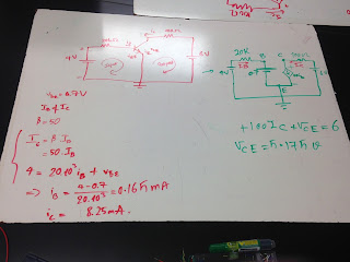
Assuming IB = (Vawg - V(BE)) / 100k , β = IC / IB , V(BE) = 0.7 v => IB(1)= 0, IB(2)=8uA, IB(3)=18uA, IB(4)=28uA, IB(5)=38uA. 

Based on this circuit, we set-up the experiment. Note: for many people, including me at first. who do not know what channel 1 and 2 are used for, they are voltmeter reading the voltage drop. 


Our set-up for this experiment


The oscilloscope of Ic and Vce. IC(1)=0, IC(2)=1.9mA, IC(3)=4mA, IC(4)=6mA, IC(5)=8mA

1. The current gain Beta (IC/IB) for each device. 
B(1)= 0, B(2)= 238, B(3)= 222, B(4) = 214, B(5)= 210
2. The early voltage V(a)for its device based on the highest base current step.


  X0 Y0 X1 Y1 M V(a) B B*V(a)
1 0 0 0 0 0 0 0 0
2 0.2 1.80E-03 4.6 2.00E-03 4.54545E-05 3.98E+01 237 9432.6
3 0.2 3.90E-03 4.5 4.00E-03 2.32558E-05 1.68E+02 222 37273.8
4 0.2 5.90E-03 4.3 6.10E-03 4.87805E-05 1.21E+02 214 25926.1
5 0.2 8.00E-03 4.2 8.20E-03 5E-05 1.60E+02 210 33642
The Early voltage ranges from 40 to 160 V. According to manufactor sepcification the early voltage also range from 100 -150V

The 2N3904 is a common NPN bipolar junction transistor used for general purpose low-power amplifying or switching applications.

Conclusion:
Today is really a long lecture and experiment. We study about supermesh and its application to simplify the equation system. We do a lab about the mesh analysis. The hardest part today would be about BJT. The BJT is kind of a complex experiment. We do research to understand how we analysis a BJT and follow the lab manual careful to get the expectation results.

Thursday, March 17, 2016

DAY 8: Thevenin and Norton Theorems/ Thevenin's Theorem Lab


PART 1: THEVENIN THEOREM

Thevenin’s theorem states that a linear two-terminal circuit can be replaced by an equivalent circuit consisting of a voltage source VTh in series witha resistor RTh , where VTh is the open-circuit voltage at the terminals and  RTh is the input or equivalent resistance at the terminals when the independent sources are turned off.


The simplified circuit and formula based on the Thevenin Theorem


The practical problem for thevenin theorem. 


the everycircuit diagram for the previous practical problem


the professor's guidance by using Thevenin Thereom


Another Thevenin practical problme. 

Part 2: Thevenin Lab

Purpose: This lab helps students grasp their understanding about Thevenin Theorem. We will set-up a familiar circuit, then create a Thevenin circuit with Vth and Rth, and independent load Rl. We will calculate and do experiment to verify our calculation. 

Pre-lab: Calculation on the circuit


The solution for the Thevenin circuit: Rth = 7.4k Ohm, and Vth = 0.495V.

Procedure: 


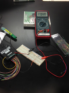
The set-up and the measured value of Vth = 0.47V. The percent difference with the calculated value: 4.25% 


The measured values of the resistors, Vth, Vab (in red), and our calculation values (in green).


Table' columns: The value of the load resistor, the measured load resistor voltage, the calculated load resistor voltage, the percent difference between the measured voltage and the calculated one.
The graph power vs. load resistance. From the graph, we estimate that when load resistor is 8.02k Ohm the power is maximum. 

Shortly, we observe the effectiveness of the Thevenin Theorem in analyzing the circuit with different load. In addition, in the end, we get the power vs. load resistance, which have non-linear relation. The maximum power is gained when the load resistor is 8.02k Ohm.

Part 3: Norton Theorem 

Norton Theorem is similar to the Thevenin Theorem, expect we have to find the In of the simplified circuit instead of the Vth. Vth equals to the open circuit voltage, while In equals to the short circuit curent. 


The practical for the Norton Theorem

Summary:
Today we learn about two more circuit analyzing techniques: Thevenin theorem and Norton theorem. These theorems is sharply effective in simplified the circuit and use this simplified circuit to calculate with different load resistors. We also do the Thevenin theorem lab to verify the theory and take a little further step to measure the power and observe the relation between the power and the load resistance.