Monday, May 30, 2016

DAY 24:: FREQUENCY DEPENDENCE/ SIGNALS WITH MULTIPLE FREQUENCY COMPONENTS LAB

PART 1: TRANSFER FUNCTIONS
Today, we discuss about the transfer functions and some relating theory of transfer functions including zeros and holes. 
An example of calculating the transfer function and its zeros and poles.


The lecture note of the professor about the above problem

We did another problems about the transfer function


The mathlab code for graph the equation above


another problems of the transfer function 

PART 2: SIGNALS WITH MULTIPLE FREQUENCY COMPONENTS LAB
Purpose: This lab aims to verify the theory about the transfer function when applying the multiple frequency source/ waveform generator. 

Pre-lab:

The schematic circuit of the lab. From our calculation, we expect,
The high frequency, then the capative impedance close to zero, the Vo/Vi = 0
The low frequency, then the capative impedance close to infinite, the Vo/Vi = 1/2.

Creating the multiple frequency waveform generator.

Vin and Vout of multiple frequency waveform generator. The results are the same as we expected. The high frequency, the ratio Vo/Vin=0. The low frequency, the ration Vo/Vin =1/2

Creating the sweep waveform generator

The result of the sweep waveform generator. The results are the same as we expected. The high frequency, the ratio Vo/Vin=0. The low frequency, the ration Vo/Vin =1/2

Conclusion:
This lecture is straightforward. We derive some transfer functions, and then do some problems to practice applying the functions in the circuit. We also did the experiment about the signals Vout/Vin with multiple frequency components. We did the lab successfully because the results from the oscilloscope meet our expectation. 

DAY 23:: APPARENT POWER AND POWER FACTOR/ APPARENT POWER AND POWER FACTOR LAB

PART 1: APPARENT POWER AND POWER FACTOR
Today, we expand the idea about power in the RLC circuit with sinusoidal sources including complex power, apparent power, and power factor. 
we derive the effective current and effective voltage

We did a problem pertaining to the effective current and voltage.


The relation between the apparent power and the average power, as well as the power factor

The angle of the impedance equal to the phase shift between the voltage and the current across this impedance.


We did a problem about the apparent power. Complex power S = Vrms.Irms* = Vrms/Z* = Irms. Z.

The summary of the complex power S (VA), the apparent power S (VA), the real power P(W), the reactive power Q (VAR), the power factor pf. 


We did a problem about the complex power.

cont. We define that the impedance is capacitive impedance. 

Another practice problem of complex power. Correcting the power factor by add the capacitor in parallel with the inductive load. We practice the a question about the power factor correction


PART 2: APPARENT POWER AND POWER FACTOR LAB

Purpose: This lab aims to practice calculation the complex power's component, and then verify the calculation with the measurement.

Pre-lab:

We calculate the theoretical values of the circuit with different resistors.

Calculation of RL circuit. 

Calculation of RLC circuit


Rl= 10ohm

Rl= 47ohm

Rl =100ohm

c

capacitor parallel

Based on the oscilloscope's data, we deduce the measured values in the table above. There is a acceptable errors between the theoretical and the experimental values about 1%-10%. The errors is acceptable since in our calculation, we assume the inductor and the capacitor is ideal rather than they has some resistor in reality. 

Conclusion:
We have built a number of equations relating to the complex power and analyzed the method to correct the power factor and gain the unity power. Moreover, we also did the experiment to practice calculations of the complex power problems. 

Day 21:: Sinusoidal Analysis/ Phasor Lab

Today, we discuss how to apply the circuit analysis technique we have studied before and the phasor techniques to find the steady-state response of circuits with sinusoidal sources.
Part 1: 
Nodal Analysis
Nodal analysis can apply to the sinusoidal sources circuit the same way we did before. Only difference is we may calculate with complex number. This 
write down nodal equations at two essential nodes. 

do the algebra work to find the voltage at two essential nodes. 

Mesh Analysis


write down KVL for each loop. I3 is given, then solve the system to find each current. 


Part 2: Phasor Lab 

The cut of frequency wc=R/L, 10*wc , (1/10)*wc. 
In RL circuit, VL leads I, f increases, then the phase shift increases. 

The cut off frequency, phase shift between Vl and I is about 45, and the Vl leads the current. 

The results from experiments.

wc (w-cut-off)

phase shift (i-vl) = -45

10*wc

phase shift = -84.28

wc/10

phase shift= -5.7


Superposition 

Since ac circuits are linear, the superposition theorem applies to ac circuits the same way it applies to dc circuits.  The theorem becomes important if the circuit has sources operating at different frequencies. In this case, since the impedances depend on frequency, we must have a different frequency-domain circuit for each frequency.  The total response must be obtained by adding the individual responses in the time domain. It is incorrect to try to add the responses in the phasor or frequency domain.

Source transformation 
the review of source transformation
Thevernin and Norton Equivalent circuits

We transform the circuit to the impedance form. 
To find V Th , we apply KCL at node 1 to find I0.  Then apply KVL to the right hand loop. Vth = 55, -90. 
To find Zth, remove the independent source and connect an arbitrary fixed current source (In this case 3A since it makes the math easy) to terminals a and b, 


Sunday, May 22, 2016

DAY 22: AC Op Amps and Oscillators/ No lab

Part 1: Op Amp Circuits
Today, we discuss about the op amp in the ac circuits and oscillators. We also did a experiment about to create an oscillators. 
First, to dealt with the op amp ac circuit, we need to remember two important properties of an ideal op amp: 1. No current enters either of its input terminals, 2. The voltage across its input terminals is zero.

We did a practice with an op amp in the ac circuit. 
Oscillators. 
An oscillator is a circuit that produces an ac waveform as output when powered by a dc input.
In order for sine wave oscillators to sustain oscillations, they must meet the Barkhausen criteria:
1. The overall gain of the oscillator must be unity or greater. Therefore, losses must be compensated for by an amplifying device.
2. The overall phase shift (from input to output and back to the input) must be zero.
The Wien-bridge oscillator 


feedback ratio is (V2/V0) = Zp/(Zp+Zs), 
which Zs= R1+Zc1, Zp = R2//Zc2. 
Based on the 2nd Barkhausen criterion, V2 must be in phase with Vo, which implies that the feedback ratio is purely real, the imaginary part must be zero. Then we deduce the ratio with the assumption R1=R2=R, and C1=C2=C, the feedback ratio is 1/3. 
Based on the 1st Barkhausen criterion, the op amp must compensate by providing a gain of 3 or greater so that the overall gain is unity or greater than 1. 
Vo/V2 = 1 + Rf/Rg = 3 => Rf = 2Rg


 Part 2:  The Op Amp Relaxation Oscillator Lab
Purpose: The lab aims to create an op amp relaxation oscillator with desired frequency.

Theory and Pre-lab
This is an op amp relaxation oscillator. 
It operates as the following process. Let’s consider
that the voltage Vplus is larger than voltage Vminus . The voltage on the non-inverting input of the
OP AMP is larger than the voltage on the inverting input. The OP AMP will try to amplify the
difference between the input voltages with a very large non-inverting voltage gain, causing the
OP AMP output voltage to saturate at the positive supply voltage VCC (+ 15 Volts).
When the situation is reversed and voltage Vminus is larger than voltage Vplus , the voltage
on the inverting input of the OP AMP is larger than the voltage on the non-inverting input. The
OP AMP will try to amplify the difference between the input voltages but now with a very large
inverting voltage gain, and the OP AMP output voltage saturates at the negative power supply
voltage VEE (-15 Volts). 

The period of oscillation is given by the expression
T = 2RC ln {(1+B)/ (1-B)} seconds, B=R1/(R1+R2).

Our desired frequency is 158Hz. Based on the above formula, we calculate the resistor required R is 2880 Ohm provided R1 = R2 = 1kOhm. 
The period is T=1/f = 6.329ms

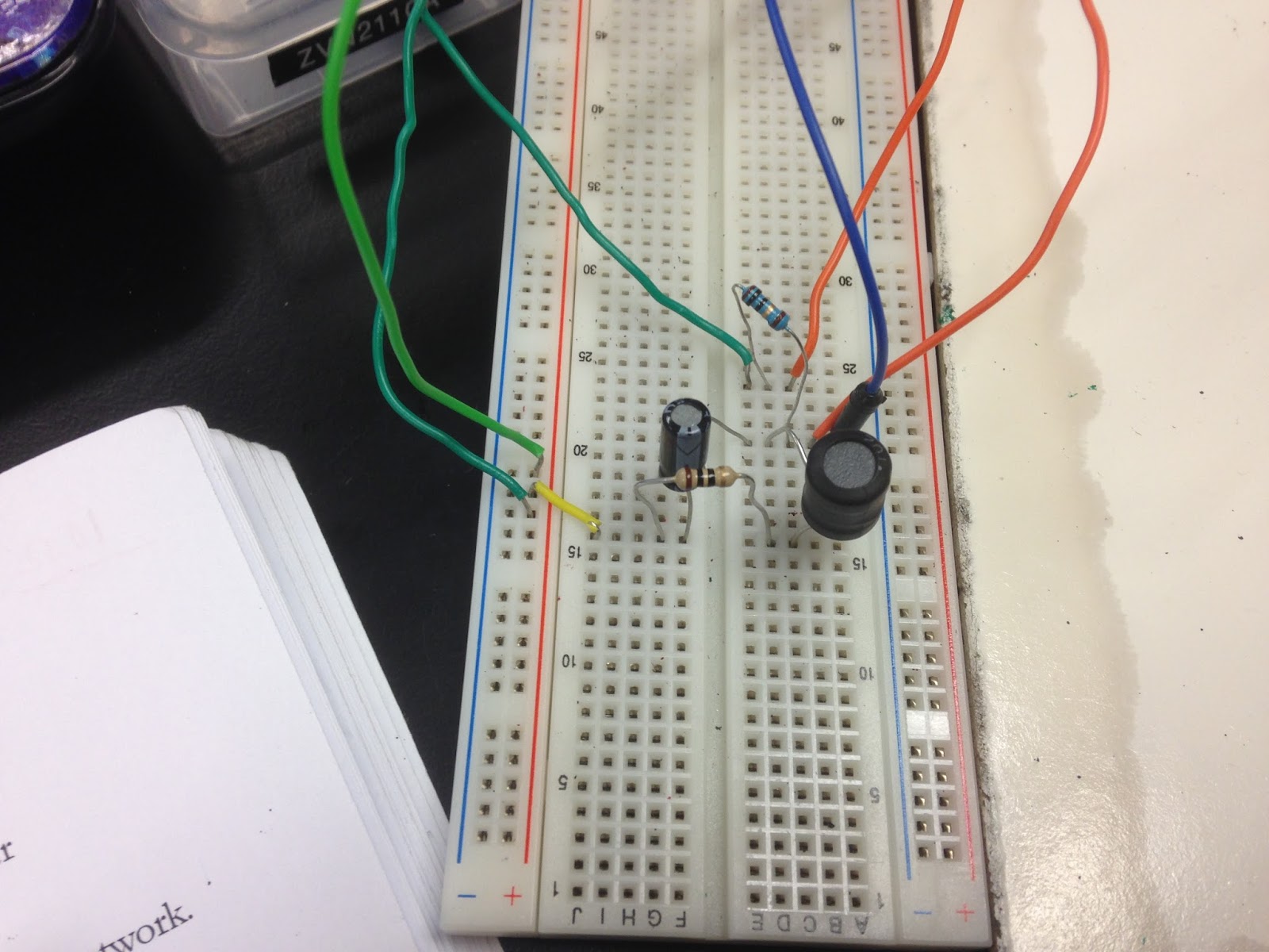
The set-up for the relaxation op amp oscillator. 

The oscillators has the period meets with our calculations: periods is about 6ms.
The measured values match with the desired value, percent error is 4%. 

Part 3: Instantaneous and average power


This shows us that the instantaneous power has two parts. The first part is constant or time
independent. Its value depends on the phase difference between the voltage and the current. 
The second part is a sinusoidal function whose frequency is 2ω, which is twice the angular frequency of the voltage or current.

the graph of the instantaneous current, voltage, and power. The period of the instantaneous power is half of the instantaneous current and voltage. 

The average power
Define: 
The average power is the average of the instantaneous power over one period

save image
After substituting the p(t), the average power is 


save image
In two special case, 
1. when the current and voltage are in phase θ v = θ i, the circuit is purely resistive,  P = ½ V m I m = ½ I2 mR = ½ | I | 2 R

2. When θ v − θ i = ± 90, the circuit is purely reactive. P = ½ V m I m cos (90) = 0. 

Conclude: A resistive load (R) absorbs power at all times, while a reactive load (L or C)
absorbs zero average power. 


We did a practice to calculate the power of each element in the above circuit. We convert the circuit into frequency domain, then find the currents in each elements, then find the average power of each element.

Maximum average power transfer

After analyzing the Thevenin equivalent of the circuit with the load impedance.
ZL = Rl +jXL,
Zth = Rth +jXth
We conclude,
For maximum average power transfer, the load impedance ZL must be equal to the

complex conjugate of the Thevenin impedance ZTh.
ZL = Rth - jXth.
then the maximum average power is P = (Vth^2)/(8Rth)
We do a practice to find the Zl to gain the maximum average power for this circuit. First, we find the thevenin impedance by short circuit the independent voltage source and open circuit the independent current circuit. Second, the conjugate of the Thevenin impedance is the load impedance gaining maximum average power. 

Conclusion:
Today, we discuss more about the AC source circuit. We practice to analyze the AC circuit including an op amp. We also study about the oscillators and make a relaxation op amp oscillator with the given frequency. We did the experiment successfully with the agreement between the measured value and the given value. Additionally, we discuss about the instantaneous power and the average power P = 1/2 * Vm*Im*cos(θ v − θ i) which is independent from time. We also deduce the thevinen equivalent to find the load impedance Zl = Rth -jXth  gaining maximum average power. Pmax = (Vth^2)/(8*Rth)