Today, we advance our method to analyze an sinusoidal source RLC circuit. We discuss how to apply Ohm's Law, KCL, and KVL into the impedance analysis.
The rattio of the phasor voltage and phasor current of R,L,C
impedance and admittance summary of R,L,C
The relation between polar and Cartesian coordinate, the relation between the impedance and admittance
We did a practice problems to apply the phasor and impedance in find the voltage and current in the circuit. We transform the function from time domain into frequency domain to calculate, and then transform back to the time-domain.
Part 2: Impedance Lab
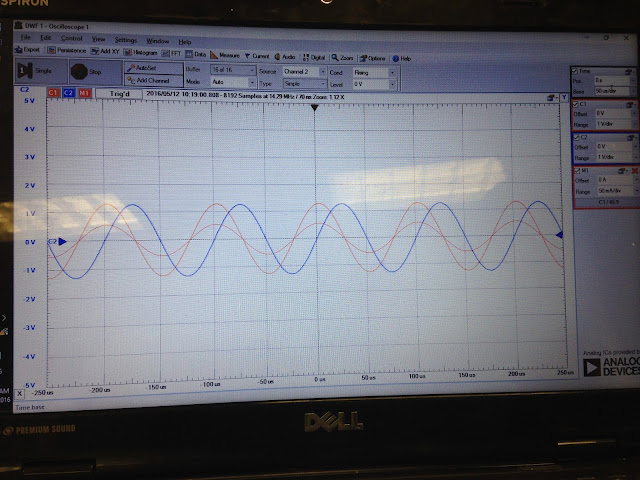
Purpose: The lab aims to verify the impedance theories and observe how the frequency will affect the Vout, Gain - the ratio between Vout and Vin, the phase shift between Vout and Vin. We will do the experiment on three elements resistor, inductor, and capacitor with three different frequencies 1kHz, 5kHz, 10kHz to compare the corresponding results.
Pre-lab:
1. Resistor
From our the theory, the circuit which only has resistors does not have the imaginary part of the impedance, so the frequency will not effect the impedance of the circuit. Therefore, the gain the will be the same regardless of the frequency's changes; the phase shift between the Vout and Vin is 0.
I=(r,phil)=(0.014,0)
I=(r,phil)=(0.014,0)
1kHz
5kHz
10kHZ
We observe the same effect from the experience. There is no phase shift, and the gain is slightly different, 4% error.
2. The inductor
From the theory, in the circuit has inductor the frequency will affect the impedance of the inductor ZL=jwL. The greater the frequency is, the larger the inductor impedance is. The Zeq = ZR+ZL. the ratio = Vout/Vin = ZL/Z= G/phil, which G, phil are respectively the Gain, and the phase shift between the Vout and Vin.
f=1kHz, ZL/Z= (r,phil)=(0.135, 82.2), G= 0.135 phase shift = 82.2, I=(0.043,-7.79)
f=5kHz, ZL/Z= (r,phil)=(0.56, 55.62), G=0.56.phase shift = 55.62, I=(0.036,-34.4)
f=10kHz, ZL/Z=(r,phil)=(0.80, 36), G=0.8 phase shift = 36.16, I=(0.026,-53.85)
Observably, as the frequency increase, the gain increase and the phase shift decreases. Graphically, we has
The phase differences among the Z, ZL, ZR is similar to the phase differences among Vin, Vout, VR. As the f or w increase, ZL increases, phil decrease, the gain (Vout/Vin) or cos(phil) increases. The positive is clockwise. Vout leads Vin value of phil
5kHz, G=0.5, phase = 51
10kHz, gain= 0.75, phase = 29
We observe the same phenomena with the theory. The gains and the phase shifts are respectively close to the theory's values. The errors are about 8%-10%
3. The capacitor.
From the theory, in the circuit has inductor the frequency will affect the impedance of the capacitor ZC=-j/(wC). The greater the frequency is, the smaller the capacitor impedance is. The Zeq = ZR+ZC. the ratio = Vout/Vin = ZC/Z= G/phil, which G, phil are respectively the Gain, and the phase shift between the Vout and Vin.f=1kHz, ZC/Z= (r,phil)=(0.99, -6.78), G= 0.99 phase shift = -6.78, I=(5.12e-3, 83.22)
f=5kHz, ZC/Z= (r,phil)=(0.85, -30.7), G=0.85.phase shift = -30.7, I=(0.022, 59.29)
f=10kHz, ZC/Z=(r,phil)=(0.64, -49.91), G=0.64 phase shift = -49.91, I=(0.033, 40)
Observably, as the frequency increase, the gain decrease and the phase shift increase negatively. Graphically, we has
The phase differences among the Z, ZC, ZR is similar to the phase differences among Vin, Vout, VR. As the f or w increase, Zc decreases, phil increase, the gain (Vout/Vin) or cos(phil) decreases. The positive is clockwise. Vout lags Vin the value of phil.

1kHz, G = 0.90, phase = -7.2
5kHz, G=0.85, phase=-30.6
We observe the same phenomena with the theory. The gains and the phase shifts are respectively close to the theory's values. The errors are about 8%-10%
Part 3: KIRCHHOFF’S LAWS IN THE FREQUENCY DOMAIN
We did a problem apply the KVL, or voltage divider in the frequency domain.
We did another problem for the KVL, the phase between Vout and Vin for the R=Xc is -45.
Conclusion:
We learned a useful method to analyze the RLC circuit with sinusoidal source by using phasor and frequency domain. We also study about the impedance and realize that the Kirchhoff's laws also apply for the frequency domain. Therrefore, we can analyze and solve these circuit by KVL,KCL, voltage divider, current divider. We also do an experiment to verify the impedance theory and see how the change of frequency affect ZL, and ZC.


No comments:
Post a Comment