Current and Voltage
The first question of the semester, what will happen when the switch is on? The answer is the bulbs stay the same because there is no different voltage between the wire of the switch, or the current does not pass through this wire.
the problem for the current definition: the time rate of change of charge. We find the function of charge in term of time and derivative it to get the current in term of time.
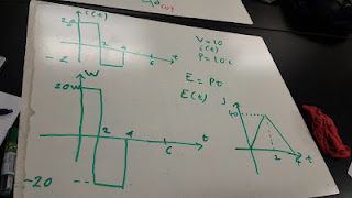
Problem for the power and energy. From the graph i vs. t, we get the graph W vs. t and p vs.t through these formula p=v.i, and p=dw/dt => w= integral(p.dt)
From v vs.t and i vs. t graph, we get the p vs. t and w vs.t graph. we interpret the graph into the equation i(t) and v(t), then apply these formula to get the answer p=vi and w=integral(p.dt).
By applied the theory that the sum of the power in all elements is 0, we get the answer for the above problem
Lab: Solderless Breadboard, Open-circuits and Shot-circuits
Purpose:
This lab aims to give students the fundamental understanding of a
breadboard where is the open-circuit and where is the short-circuit.
Procedure:
We use wires and digital multimeter as an Ohmmeter to check
resistance in order to verify the circuits of a breadboard.
1. Firstly, we measure the resistance between two holes in the
same row. The DMM reads 0.4 Ohm , so it is a short-circuit.
2. Secondly, we measure the resistance between two holes on
opposite sides of the central channel of the breadboard. The DMM reads infinite Ohm , so it is an open-circuit.
3. Thirdly, we measure between two arbitrary holes in the
breadboard. The DMM reads infinite Ohm, so it is an open-circuit.
4. Lastly, we measure between holes connected by a jumper wire. The
DMM reads 3 Ohm, so it is a short-circuit.
We have the results in the white board. 1 and 4 are the short-circuits, while 2 and 3 are the open-circuits.
In conclusion


No comments:
Post a Comment