Today, we discussed about the circuit RC or RL. We found the formula for current, voltage across the capacitor, and the inductor in each circuit.
First, we reviewed the inductance equivalent. Inductors in series and parallel circuit act as the resistors in series or parallel.
Then, we analyzed a RC circuit free source, and measured the current across the capacitor. The voltage stored in the capacitor, we began to decrease by the time as v(t)=Vo*e^(-t/T), T=RC.
Mathematically, the voltage totally disappeared when the time is infinite. However, in terms of engineering, 1% voltage left is enough to consider that almost the voltage is gone. For the v(t)/Vo=1%, we have the time equal to 5*T, T=RC.Thus, when time equal 5T, we consider that the voltage is disappeared.
the formula for the power of the circuit.
In the ranges, R=[Rmin, Rmax], C=[Cmin, Cmax], the time constant min = Rmin*Cmin, the time constant max=Rmax*Cmax.
Part 2: Passive RC and RL Circuit Natural Response Lab.
Purpose: The lab aims to help students verify their theory about the RC and RL circuit with the experiments. We will change the voltage by using the square voltage supply and disconnecting a DC. The will we compare the theoretical and experimental value of the time constant. T=RC or T=L/R.
Pre-lab:
We calculated the Theverin resistance of the circuit by replacing the voltage sources by short circuit or the current voltage by the open circuit. Then, R1//R2, We choose R1=1kOhm R2=2.2kOhm => Req= 0.6875kOhm. The time constant T=Re*C= 15ms
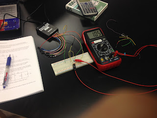
Then we set up the RC circuit according to the instruction. Use channel 1 to measure the voltage across the capacitor, and use the oscilloscope to get the voltage signal.
First one we experiment by disconnecting the DC. We get the signal as the picture. The voltage across the capacitor almost disappeared in 100ms, and we know it by the previous analysis the time for almost this appearing about t=5T. So the T= 100ms/5=20ms. The theoretical is 15ms, so the percent difference is 33.33%.
Then we created the square power supply by the waveform generator.
The time constant for this experiment with a square power supply is 90ms/5= 18ms, so the percent difference is 20%.
The RL circuit:The set-up is almost like the RC, only the difference is that we replaced the capacitor with a inductor. The time constant is T=L/R= 1mH/0.687kOhm=1.45us.
We replaced the capacitor with a inductor
The time constant for DC disconnection is T= 10us/5=2us. So this is off from the theoretical value. the percent difference is 40%
For the square power supply, the time constant is 5us/5=1us, which is close to theoretical value. the percent difference is 31%.
The difference is expected because the theoretical values are for a ideal capacitor and inductor. Because the real capacitor and inductor do not trapped the energy ideally, so we see there is the difference in the time constant. Moreover, as the theoretical the current in a inductor, or the voltage of the capacity totally disappear when the time is infinite. We assumed that that the appropriate time so that the current and the voltage are almost gone is 5T. There are two factors that affect our measurement.
Conclusion:
We discussed and analyzee the RC and RL free source. We also did some problem to gain the fundamental ideal how these elements work and deal with the resistors on the circuit. For the lab, we spent time working around to get the desired signal on the oscilloscope. We verified the natural response of the capacitor in RC circuit and the inductor in RL circuit. Due to the non-ideal capacitor and inductor as well as our assumption, our experimental values are likely different from the theoretical values. Despite that we still get the desired signals which express the natural response of the capacitor resisting to the change of voltage, and inductor resisting to the change of current. In the charging phrase or the very beginning moment, we will consider the inductor as the short circuit and the capacitor as the open circuit.


No comments:
Post a Comment